Unit 69
For this unit I have to create one asset that is going to be a main feature of the game I am building for unit 18, it has to be below 8,000 trails, fully textured and have a high to low poly bake as well.
|
Uv maps UVs are two-dimensional texture coordinates that use the vertex information from the model geometry. UVs are important to the model because it tells the model how to apply the texture onto the surface. The XYZ axis are already used in the 3D space, we have to use U and V for the axis in the 2D space. So when these two are applied together U and V axis of the 2D texture it projects its coordinates onto the 3D models axis of XYZ. In the image below you can see 10 vertex selected in the model and in the UV map you can see where it corresponds to the 2D texture 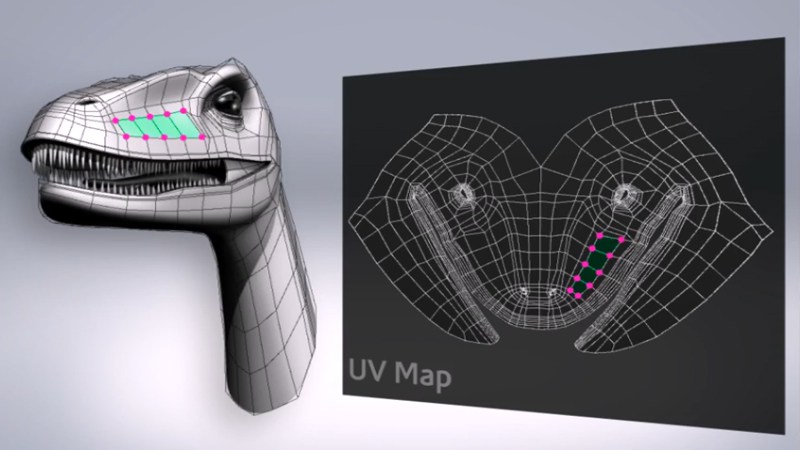 The UV map needs to unfold and flattened out and have no overlapping UV coordinates to stop texture deformations. Also, using a checked texture is ideal so that you can see where the texture would be stretched and if it has even squares. As shown in the image below, is bad UVs, stretched and distorted and not perfect squares 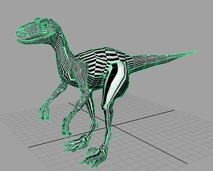 In the image show how correct UV unfolding looks like as there is no stretching or distorting. This is shown by even squares throughout the model 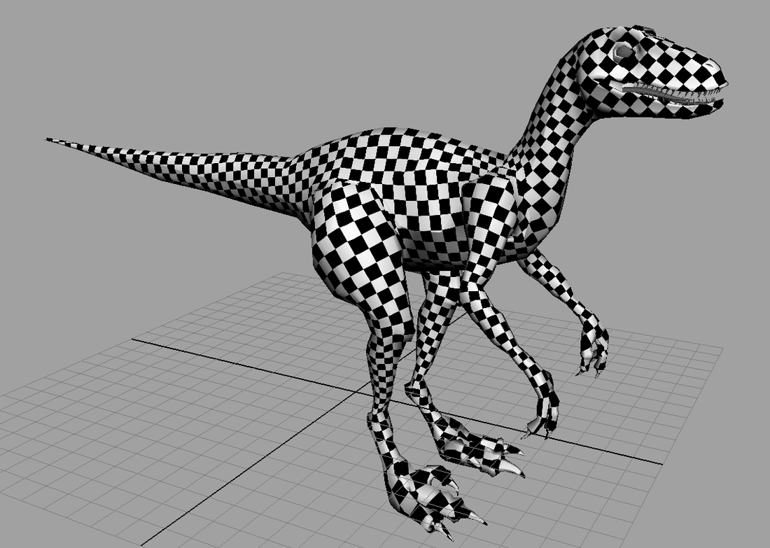 References https://biocinematics.blogspot.co.uk/2010_04_01_archive.html http://blog.digitaltutors.com/understanding-uvs-love-them-or-hate-them-theyre-essential-to-know/ Lightmaps Lightmaps are based off the models UV texture coordinates placed into a new UV layer. They are pre-rendered in the game engine and turned into a grey scale texture. When a light shines onto the model has cast a dark grey shadow of the diffuse texture coordinates. Lightmap UV's need more space between each shell so there is no overlapping and cause a shadow bleeding as shown in the image below what happens when lightmaps overlap and cause a shadow bleed. 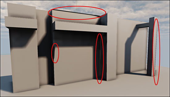 The image below shows how correct lightmaps render in the game engine. 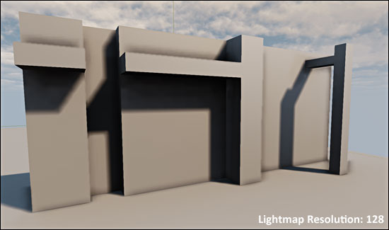
1 Comment
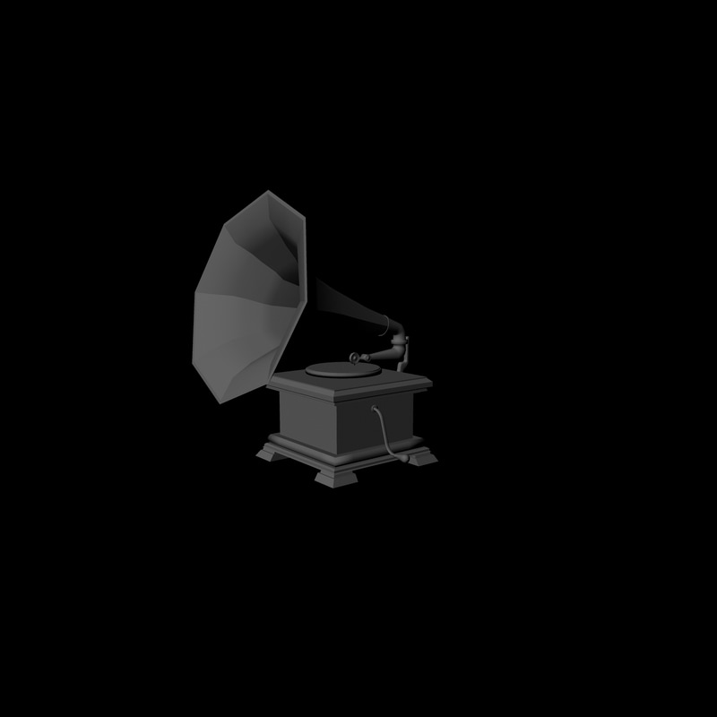
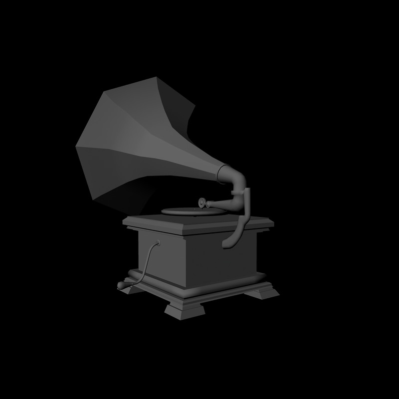
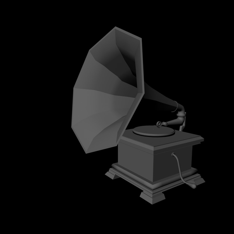
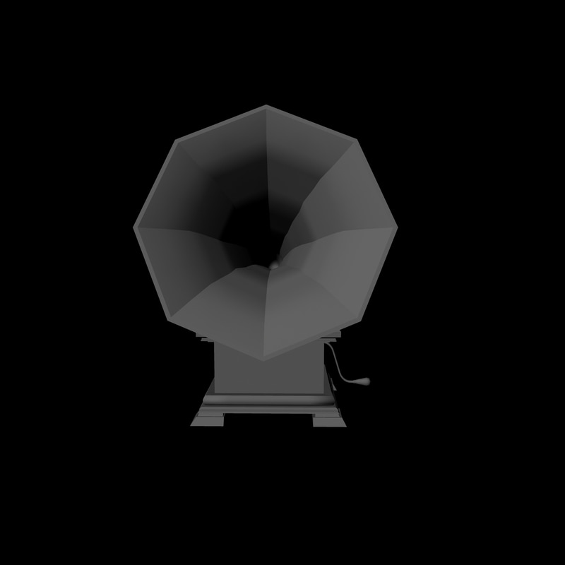
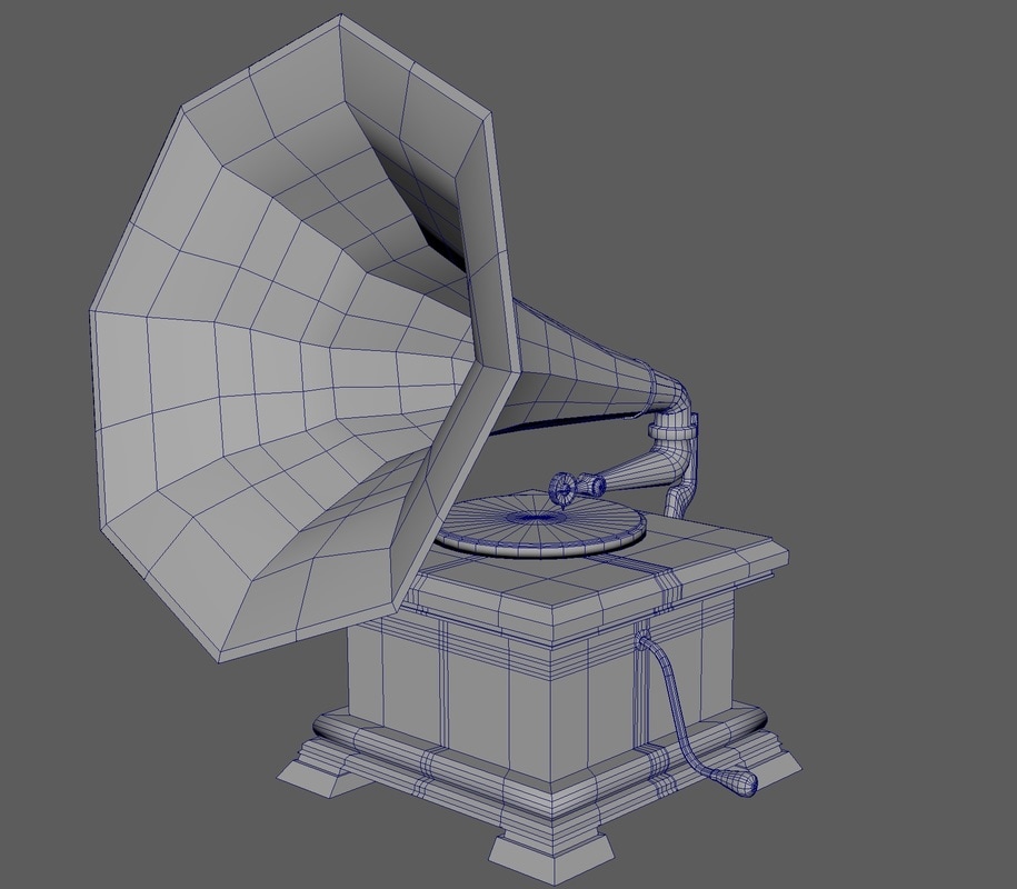
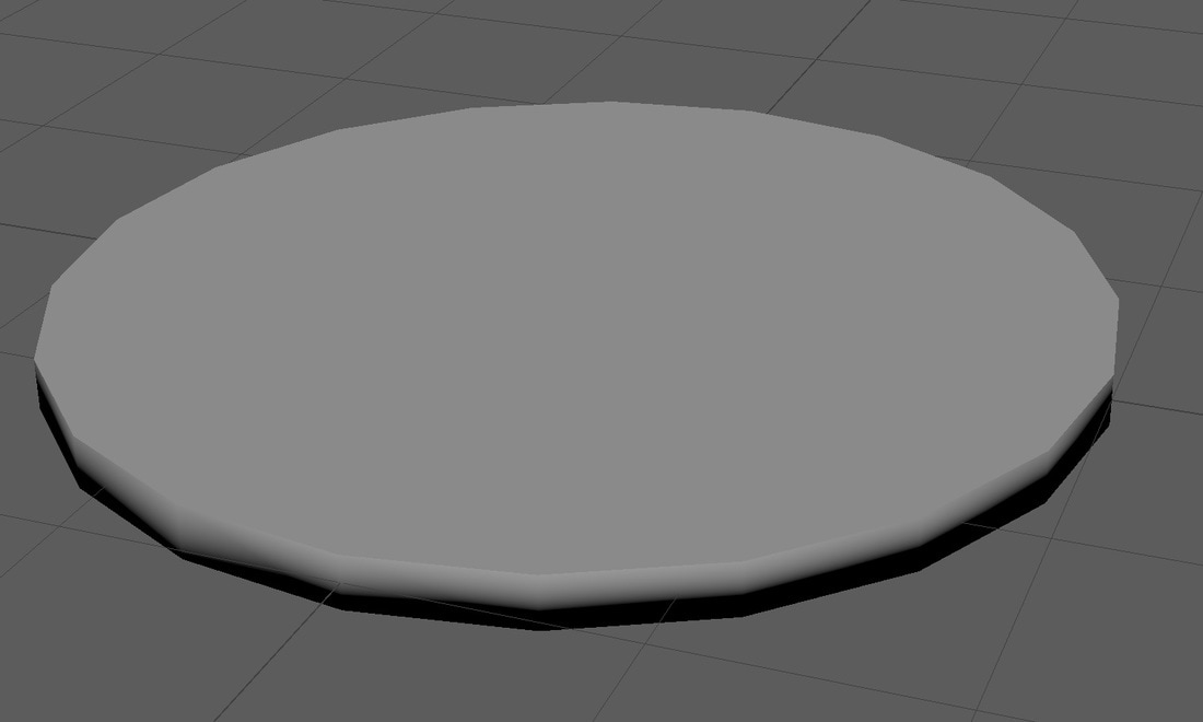
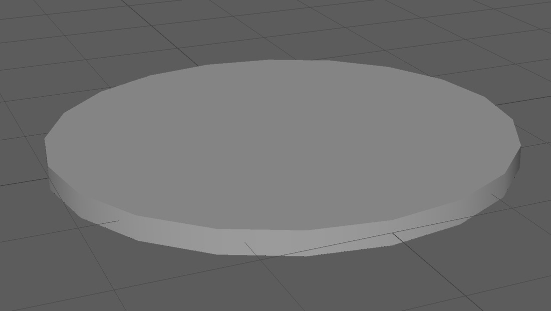
After researching good and bad topology I started to make my gramophone, I found a reference photo to use as guidance which I imported into Maya onto a background plane. 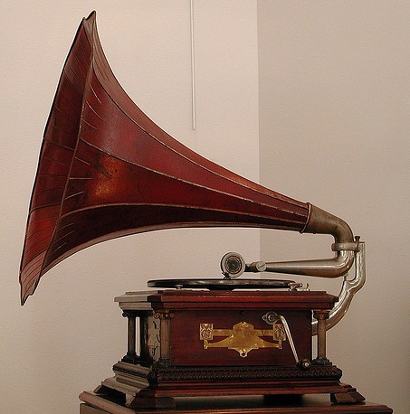 I decided to break the model down into four sections and model them all sepertley and then combinded them all together. I started off with the horn using a tube with 8 sides, I made one end big and wide and the other end the pursuit and resized the remaining edges to give a smooth transaction. After that I added an edge loop to the smaller end and extruded out from this to make a lip on the metal. I then got another tube and used a deform nonlinear bend, I used this process for the arm that attaches the horn to the box. After that I added extra edge loops to the horn and target welded the two together. Then I used two cylinders and target welded these to the end of the new horn. I then created the box using a cube, I added edge loops around the top and bottom of the box and then extruded out from these to add a bevel and detail to the top and bottom edges. on the bottom I added extra edge loops after this and moved the edges out to give the effect that there is a small smooth bevel. I then extruded the feet from the bottom of the cube and positioned the bottom edges out to give a sloping effect. After this i made the turn handle by using a cylinder and using the nonlinear bend tool again and then extruded out at the end to make the handle. The difficult part was attaching a cylinder to a cube and i had to place a lot of edge loops on the cube to connect the handle to the box The final bit of the model I made was the turntable, which is a cylinder that I used extrude on to add the effect that is a disk on the turntable and a pin it rotates around. I decided to not attach this to the rest of the model as it can be used as moving parts. For all the cylinders I removed the pole and bridged the caps and then used the Multi-cut tool to cut two or 3 lines in the centre to make the cap of the cylinder have quads for subdivided later. I also used soft and hard edge to effect the surface normals so on the areas that are smooth e.g the tube of the horn and the handle I use the soft edge tool and for the box where there is crisp lines I used the hard edge tool. In the images below are a few render shots of the model and a wireframe image The main tools i used inside maya to create my gramohpone are:
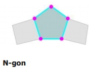
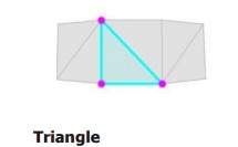
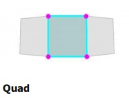
The tools that I used the most were the edge loop tool, it was great for adding extra lines to the geometry so I could connect each section to each other. I also found targeted wield and the bridge tool for connecting faces and vertices together, as well as recapping the top of a cylinder and using the append to polygon to finish the ends that I could not bridge. The extrude tool was also another major tool for me, I used it a lot to extrude out of shapes to add more geometry to either add extra detail or more shape. Before I start to design my assets model for unit 69, I decided to research about good topology, what is the correct topology for my model and what is not correct. Topology is the components that are connected and flow around the 3D objects, these are usual faces, edges and vertexes. As I’m making a game model I should optimised it to create a good silhouette, good edge loops for better deformation (mainly for characters) and for subdividing, extreme changes between surface normals (also known as vertex normals) and good UV seams. For good topology I want my model to be quads and little as possible triangles and avoid N-gons N-gons are shapes with more than four edges, these cannot be subdivided and would break the model when tried to be generated. N-Gons are also bad for games as well when put into a game engine as the engine tries to process the n-gon and puts more strain onto the graphics card and computer. The engine turns a quad into two triangles that it can render a N-gon will require more tingles and the more triangles the more time it takes for the engine to render causing a bottle neck known as lag or fps drops. Triangles are bad when trying to subdivide as it would not be able to subdivide the triangle and causes more errors Quads are more ideal as there are four edges and can connect easily to the next face, can be subdivided with out error and can be deformed with extra edges in the area e.g. bends or limbs References: http://blog.digitaltutors.com/ngons-triangles-bad/
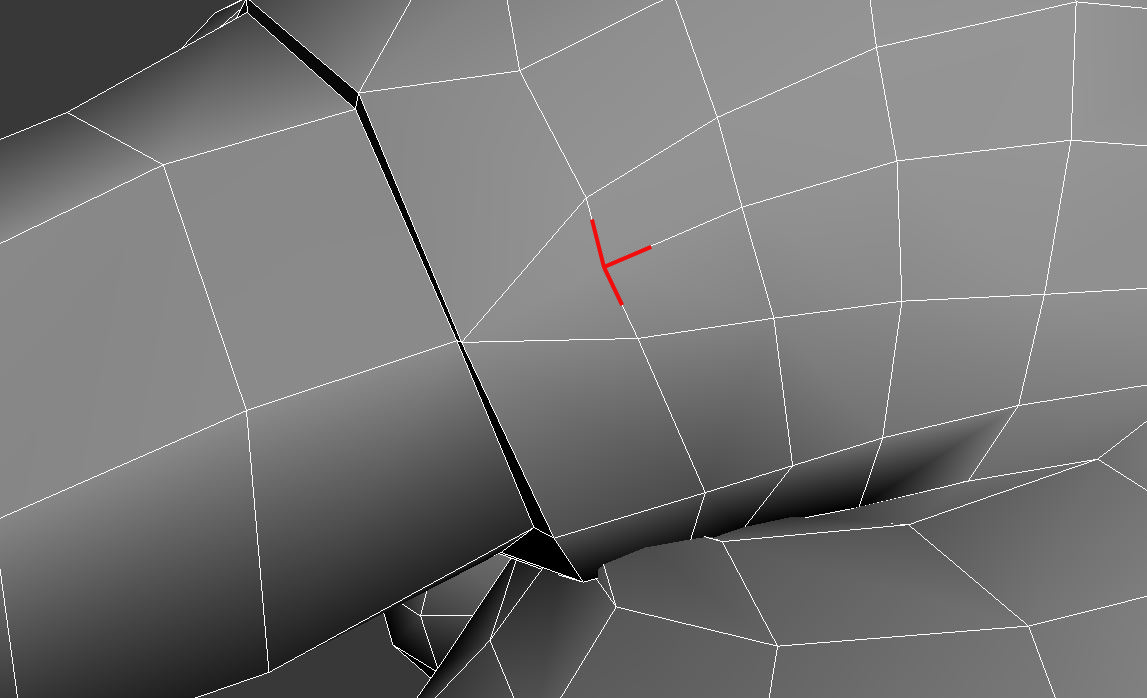
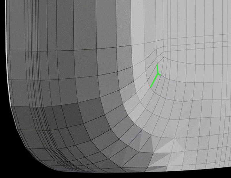
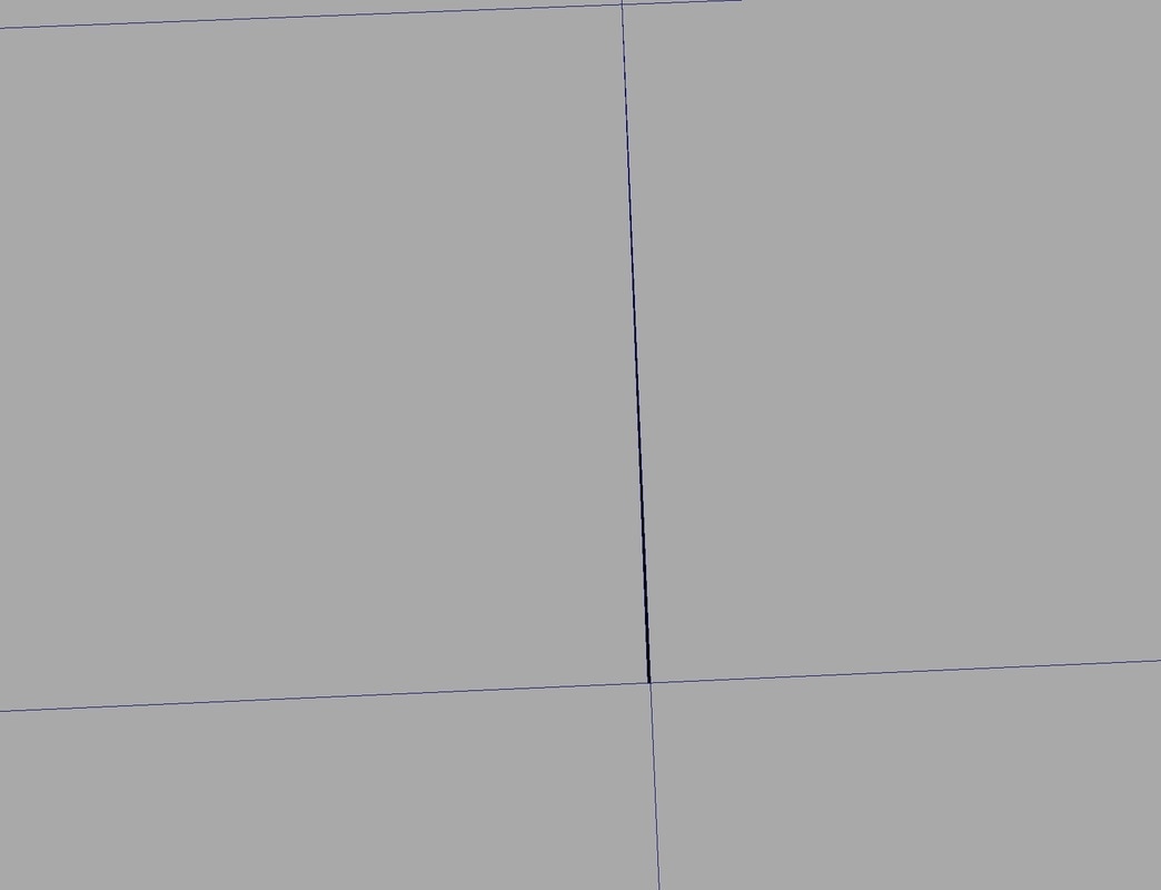
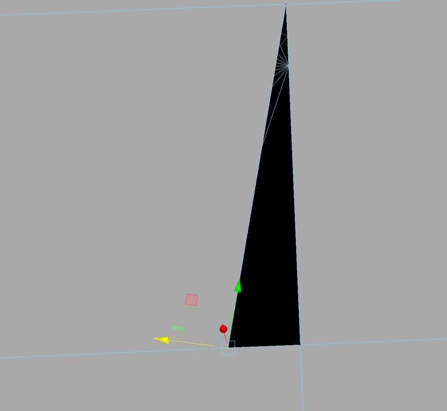
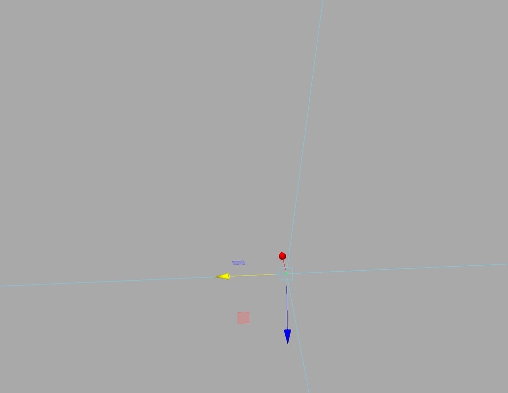
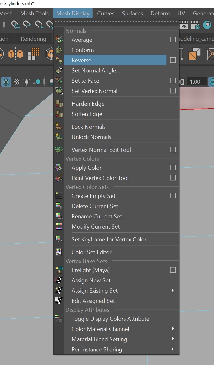
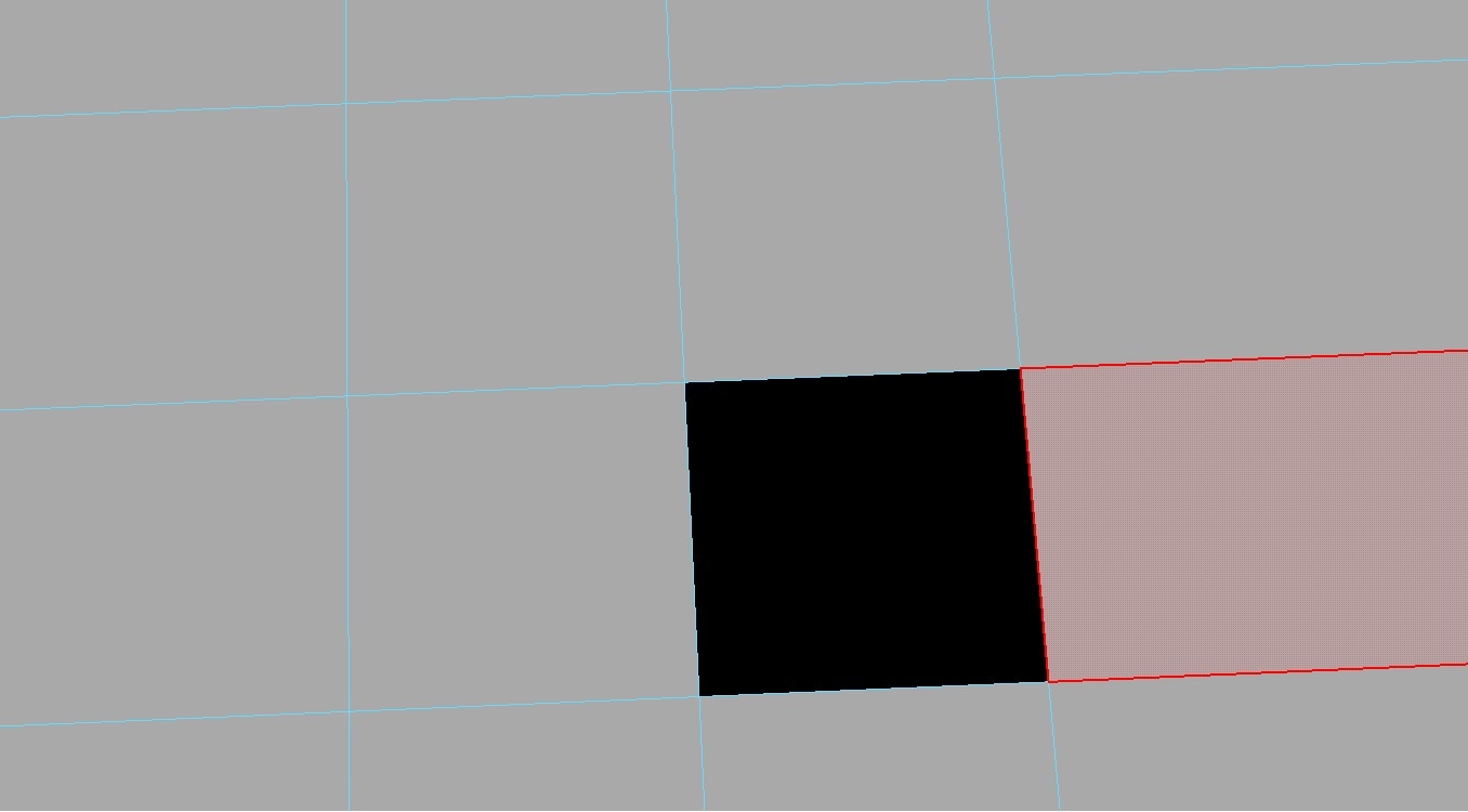
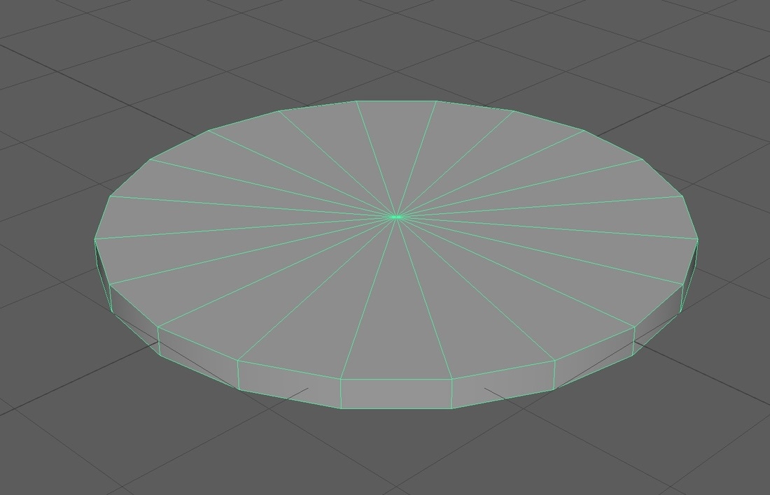
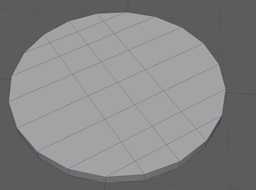
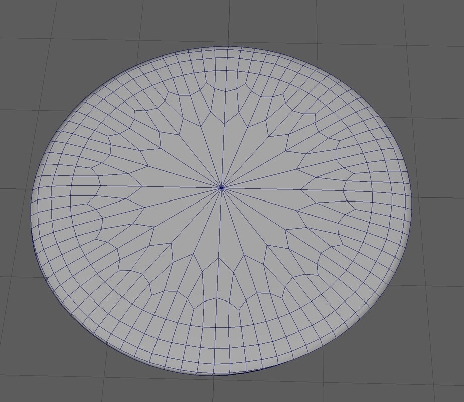
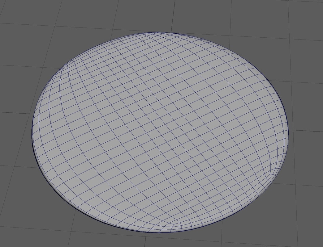
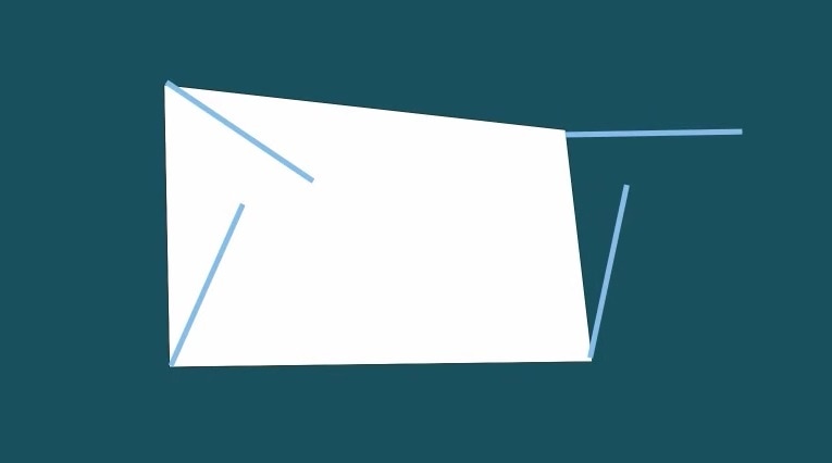
Other type (manifold Surfaces) of bad topology I need to avoid to get good topology is: T-Vertices are when you have two edges connected and form a T-shape with the edges leaving a vertex, this can cause errors if not used correct. if a T-Vertices connects into a quad I can create an N-gon and won’t have edge flow and cause bad subdivision. Best used when the model edges are flowing around a corner and T-Vertices is connected to a triangle and this created a quad. But these should be avoided if possible. References: http://blog.turbosquid.com/2013/09/05/checkmate-pro-v2-specification-t-vertices/ Doubled faces usually caused by extruding twice and causes faces to overlap or when vertices / edges are target welded to other parts of the model and causes overlapping and double faces. Holes are usually created when faces have been deleted and existing faces have not been connected via vertex or edges as shown in the photos below. Reversed faces happen when the surface normals flip to show the black underside of the face and can be easily fixed by reserving the surface normals back. Unseen faces are internal faces that we forget to delete when connecting two parts of the mesh together via mirroring, extruding or combining Reference: https://accad.osu.edu/~sconroy/accad5002/notes_geo_problems.html 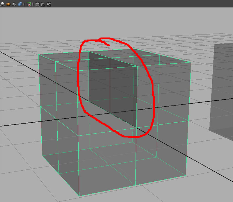 Floating vertices are when an edge has been deleted and vertexes have been left and are not connected to any other edges. these cause errors when subdividing and texturing and can cause problems when imported into the game engine. T-vertices can also be classed as this as well. 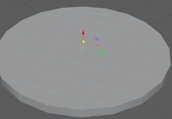 High-valence Vertex also known as poles is when 5 or more edges converge at a single vertexs, most commonly found when making a cylinder and the cap has all the edges going to one vertex. Having poles in a model will cause problems when applying a smooth or subdividing. Best way to get around this removing any poles and turn it into quads and tringles as show in the photos below, one photo with a pole and another with quads and triangles Now if add a smooth/subdivide to each of these, the pole will only subdivide so far while the quad model subdivided perfectly. These are all the different types of bad topology that I need to look out for when i am creating my model. Surface normals I also researched about surface normals so I could get soft and hard edges in my model. Every polygon includes information about how light will bounce of the face of the polygon, by changing the direction of the surface normals we can change how the light bounces of the surface creating face that look more soft or have hard crisp edge lines. Maya has lots of tools to change the surface normals, I will only be using two of these tools: mesh display > Hard edge and soft edge. In the photos below show a face with default surface normals and once that have been edited In the photos below show a model been effect by hard and soft edge |
AuthorWelcome to my blog about my game design and 3D modelling work Archives
February 2017
Categories
All
|
||


 RSS Feed
